- File size:
- 4.9 GB
- Date added:
- Apr 08, 2024 | Last update check: 1 minute ago
- Licence:
- Trial | Buy Now
- Runs on:
- Windows 10 64-bit / 11 See Autodesk's Product Support Lifecycle for support information
Inventor is a CAD software for 3D mechanical design, simulation, visualization, and documentation, turning concepts into manufacturable designs. It offers an easy-to-use toolset to rationalize and engineer design, so it can be manufactured to known characteristics.
Autodesk Inventor helps you reach the best possible design using tools that can simulate, optimize and even generate geometry based on the real-world conditions your product will see everyday. Built-in design accelerators allow you to generate more concept iterations, deliver better products, reduce development costs and get to market faster.
Inventor design automation tools allows you to generate models and drawings automatically. Inventor helps you to create accurate drawings faster than traditional 2D methods, generate engineering and manufacturing documentation directly from the digital prototype helping you reduce errors and deliver designs in less time. From day one of the design process you can visualize and communicate real world applications of your products. Inventor’s visualization tools create renderings of your products in the context of the environment they’ll be used in.
Environments. There are different environments within the Inventor: Parts, Assemblies, Sheet Metal, Drawings. They are represented as specific workspaces or modes that you can switch between to perform different tasks. Each environment has its own set of tools and features that are specifically designed for the tasks you would perform in that environment. These environments are interconnected, meaning changes in one (like a part) reflect in others (like an assembly or drawing).
File types. Inventor has three primary file types: Parts with .ipt file extension, Assemblies with .iam file extension, and drafting documents with .idw or .dwg file extension. A forth file type called the Presentation file with .ipn file extension is used exclusively for creating exploded projections of assemblies.
What’s new in version 2025:
- Parts:
- Enhanced sheet metal design: Modernized interface and enhanced direct manipulation of flanges for intuitive and efficient sheet metal design.
- Enhanced Finish feature functionality: Made adjustments to features directly in Express mode.
- Hole creation: Incorporation of the ISO 15786 standard, allowing users to design holes in strict compliance with this international standard.
- Pattern creation: Introduction of boundary patterns, enabling users to generate patterns confined within specific boundaries.
- Assemblies:
- Expanded bolted connection support: Supports assembly feature patterns, accommodating all types of assembly patterns.
- Model simplification: Addition of cylindrical envelope option for precise model simplification.
- Enhanced visualization: Separate color scene display for better visualization and management of complex assemblies.
- Drawings: Insert item numbers into drawing text, added new property type “Parts List Properties” within the Format Text dialog, background fill colors for dimensions, and new sorting options for parts lists.
- Interoperability: Seamless integration with other programs within the Autodesk ecosystem, including backward compatibility for Revit files and improved IFC file import options.
Typical workflow
- Setup: Install and launch Autodesk Inventor. Sign in with your Autodesk account if prompted.
- UI and basic concepts: The user interface in Autodesk Inventor follows the Autodesk-style, which includes standard interface elements such as the ribbon, panels, toolbars, and viewport. Familiarize yourself with the basic concepts of Inventor:
- Environments: Distinct workspaces or modes within the software that are tailored to specific tasks (Parts, Assemblies, Sheet Metal, Drawings).
- Parts: Individual components within a design, representing physical objects or objects.
- Assemblies: Collections of parts and sub-assemblies combined together to form a complete product or system.
- Drawings: 2D representations of 3D models used for documentation and communication purposes, including annotations and dimensions.
- Sketches: 2D profiles or outlines used as the foundation for creating features in parts and assemblies.
- Features: 3D shapes and operations created from sketches, such as extrusions, cuts, and revolves.
- Constraints: Rules applied to sketches and features to control their position, size, and relationships.
- Mates: Constraints used to position and align components within assemblies.
- Browser: Hierarchical structure displaying the components, features, and constraints in the design.
- Parametric modeling: A 3D modeling approach where the shapes and sizes of a model’s geometry are driven by parameters and equations, allowing for easy modification and iterations in the design process.
- Modeling techniques: Methods used to create and modify geometry, such as extrusion, revolve, sweep, and loft.
- Simulation and Analysis: Tools for testing the performance, behavior, and integrity of designs under various conditions.
- Create file: Create a new file to start your design project. Choose the type of file you want to create, such as a part, assembly, drawing, or presentation file. Usually you will start by creating a part file.
- Design part: In a part file, create a sketch and use feature tools to create 3D features from the sketch.
- Assemble parts: In an assembly file, insert parts and use constraints and mates to assemble them.
- Generate drawings: In a drawing file, insert views of the part or assembly and add annotations and dimensions to document your design.
- Technical specifications: Create bills of materials (BOMs), parts lists, and assembly instructions. They are typically not directly added to drawing files, but can be referenced within the drawings.
- Simulate and Analyze: Use simulation and analysis tools to test your designs (stress analysis, motion simulation, interference detection, etc.).
- Export and Collaborate: Save your design files and export them in various formats for sharing. Share files and track changes with team members.
- Create presentation: Prepare a presentation file with visual elements like exploded views and animations to effectively communicate design concepts and benefits, facilitating feedback and approval from stakeholders.
Gallery
Inventor 2025
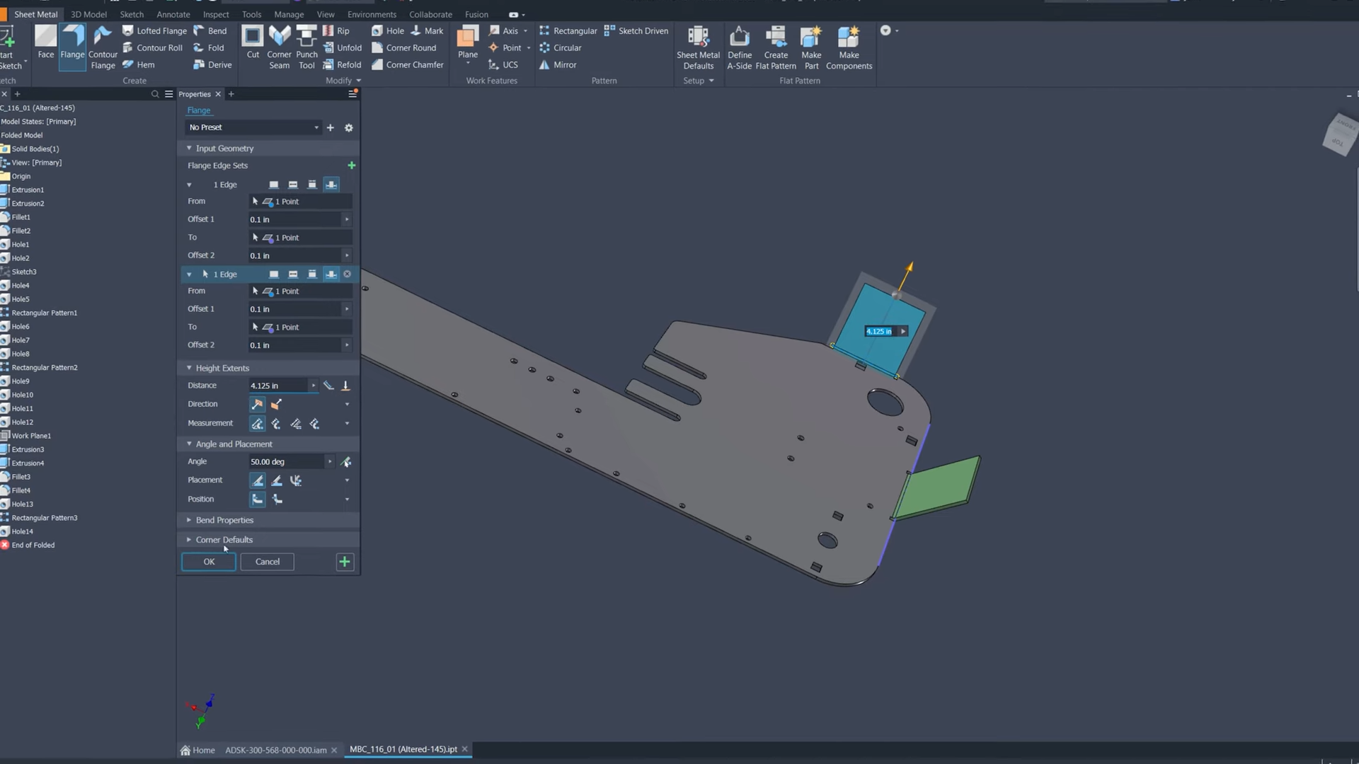
Inventor 2025: Enhanced direct manipulation of flanges. ©Autodesk
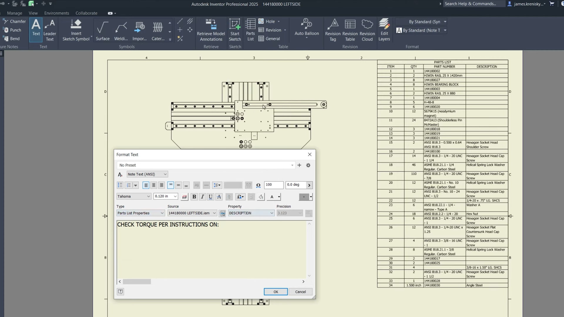
Inventor 2025: New property type “Parts List Properties”. ©Autodesk
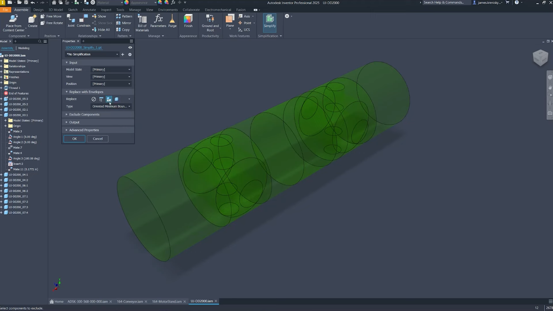
Inventor 2025: Cylindrical envelope option for more precise model simplification. ©Autodesk
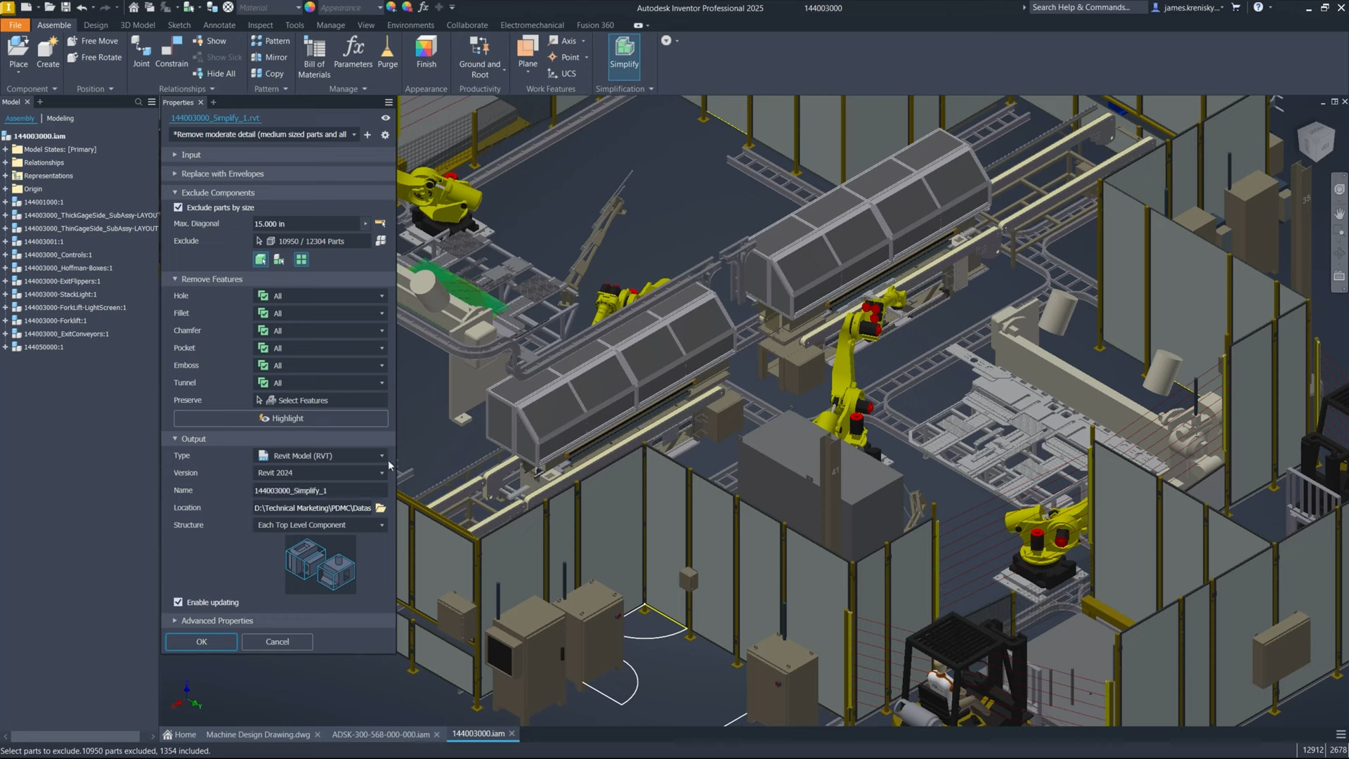
Inventor 2025: Export RVT or RFA files to earlier versions of Revit. ©Autodesk
Inventor 2024
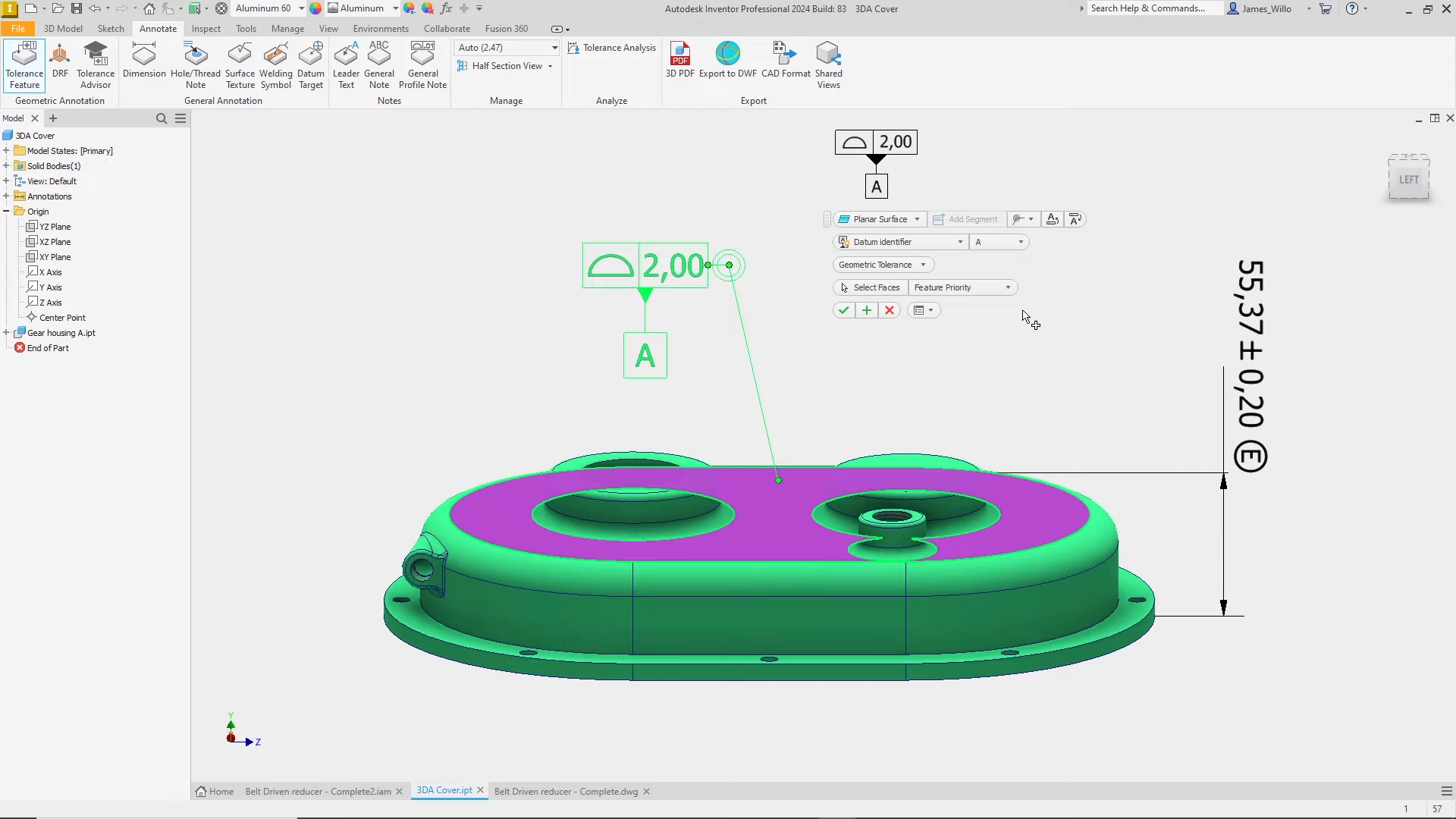
Inventor 2024: Improved 3D annotations. ©Autodesk
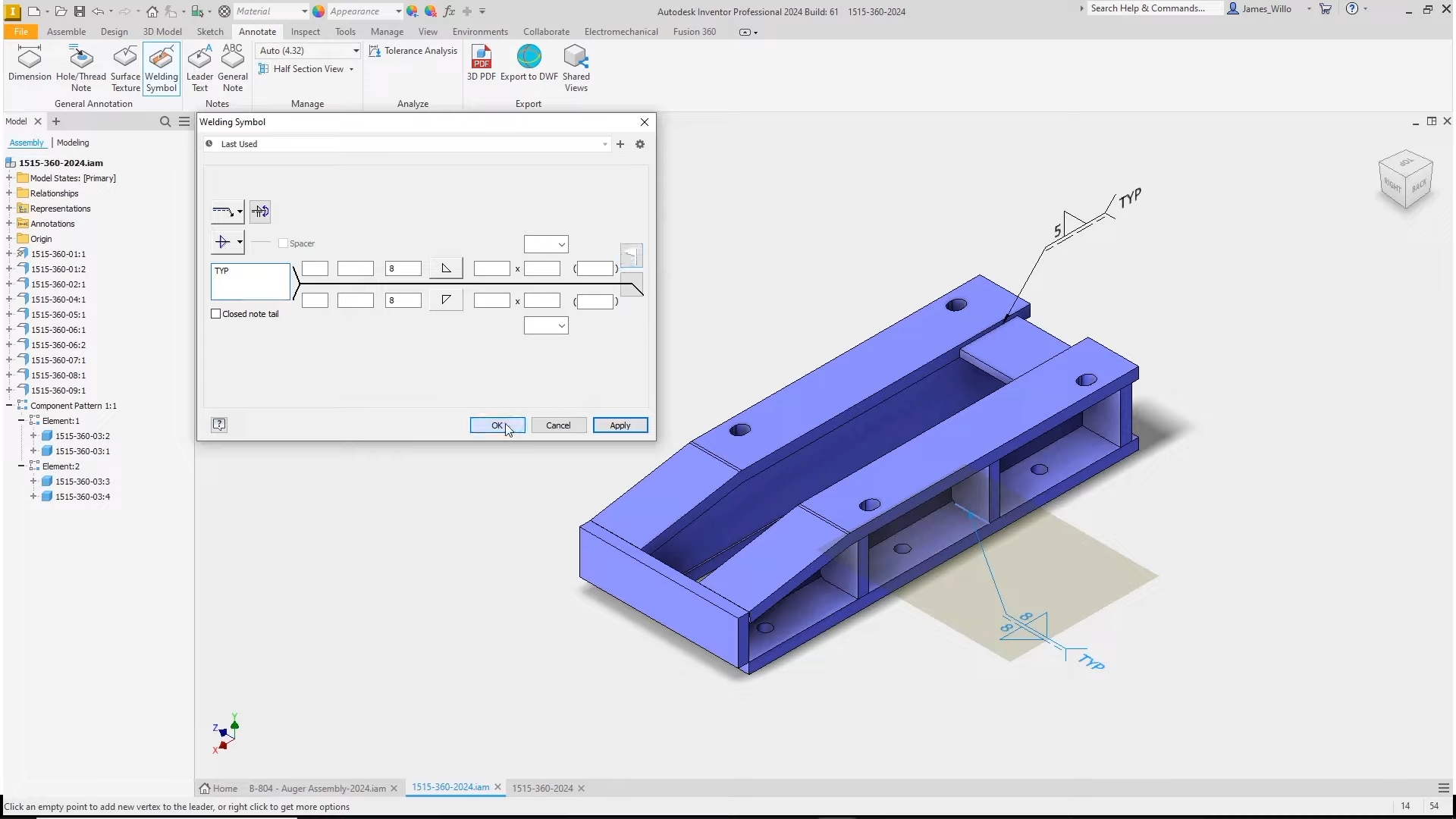
Inventor 2024: New “Welding Symbol” option. ©Autodesk
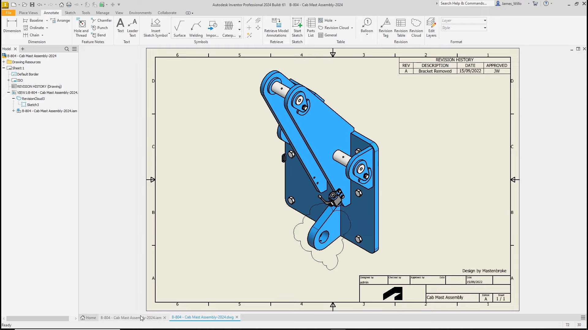
Inventor 2024: Revision Clouds. ©Autodesk