- File size:
- 661 MB
- Date added:
- Dec 20, 2021 | Last update check: 1 minute ago
- Licence:
- Trial | Buy Now
- Runs on:
- Windows 7 / 7 64-bit / 8 / 8 64-bit / 10 / 10 64-bit Windows Server 2008 / Server 2008 64-bit
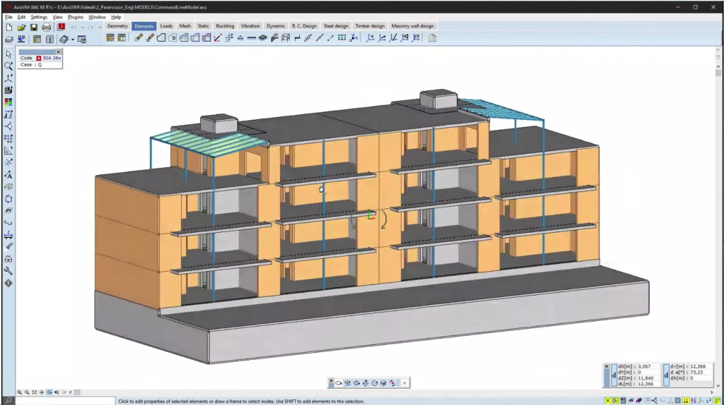
AxisVM is a finite-element program for the static, vibration, and buckling analysis of structures. It was developed by and especially for civil engineers. AxisVM combines powerful analysis capabilities with an easy to use graphical user interface. The single user interface allows users to perform from modeling, analysis, design, detailing to reporting.
AxisVM provides users with advanced analysis capabilities: linear, nonlinear, plastic static analysis; linear, nonlinear time history analysis; frequency and mode shape calculation; pushover analysis; unlimited number of equation; fast, parallel solver with multi thread and partitioned technology.
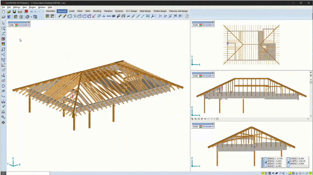
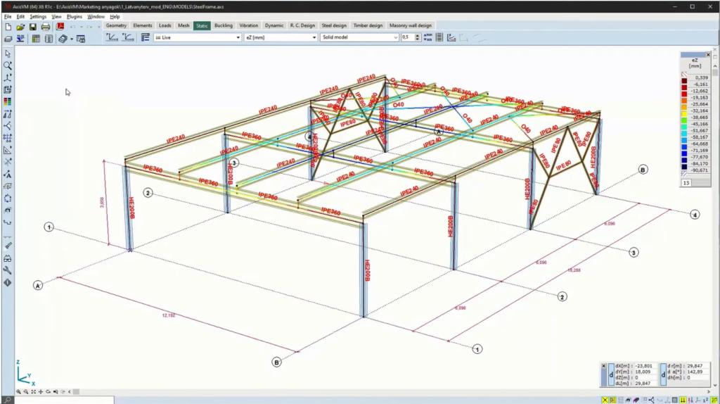
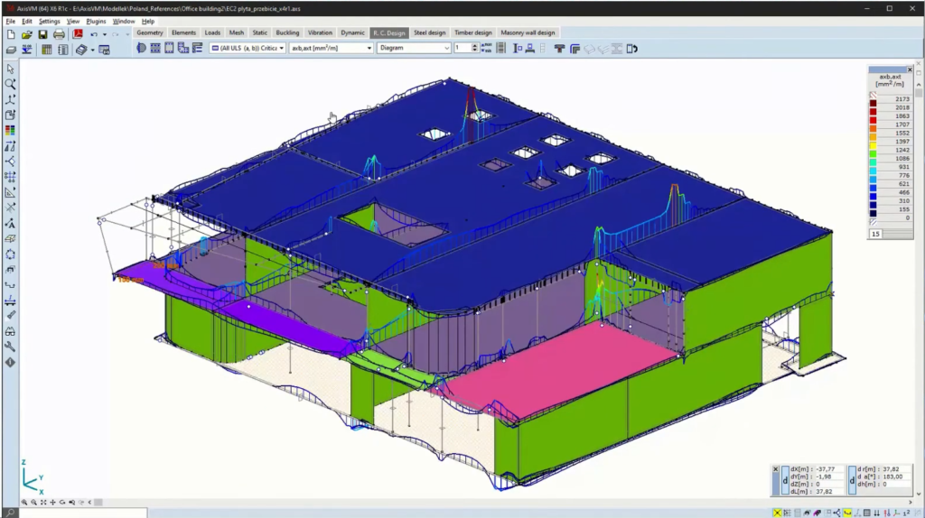
You can perform various design calculations; check steel design and optimize cross-section; design timber with softwood, hardwood, Glulam and LVL materials. AxisVM includes design modules for reinforced concrete beams, columns, plates, walls, footings.
-
- Preprocessing
- Modeling: geometry tools (point, lines, surfaces); automatic meshing; material and cross-section libraries; element and load tools, import/export CAD geometry (DXF); interface to architectural design software products like Graphisoft’s ArchiCAD via IFC to create model framework directly.
At every step of the modeling process, you will receive graphical verification of your progress. Multilevel undo/redo command and on-line help is available. -
- Analysis
- Static, vibration, and buckling.
-
- Postprocessing
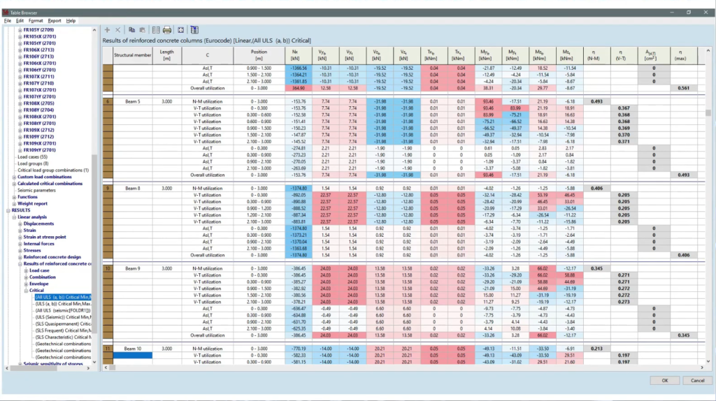
- Displaying the results: deformed/undeformed shape display; diagram, and iso-line/surface plots; animation; customizable tabular reports.
After your analysis, AxisVM provides powerful visualization tools that let you quickly interpret your results, and numerical tools to search, report, and perform further calculations using those results. The results can be used to display the deformed or animated shape of your geometry or the isoline/surface plots. AxisVM can linearly combine or envelope the results. -
- Reporting
- Reporting is always part of the analysis, and a graphical user interface enhances the process and simplifies the effort. AxisVM provides direct, high quality printing of both text and graphics data to document your model and results. In addition data and graphics can be easily exported (DXF, BMP, JPG, WMF, EMF, RTF, HTML, TXT, DBF).
AxisVM integrations
AxisVM supports the Microsoft COM technology, making its operations available to external programs.
A high-level BIM connection via IFC files or dedicated interfaces facilitates bidirectional data exchange with any BIM-based application (Archicad, Revit, Nemetschek Allplan, Tekla Structures, etc.). The Revit add-in provides for direct data exchange between Revit and AxisVM. The Tekla Add-in provides for direct data exchange between Tekla and AxisVM.
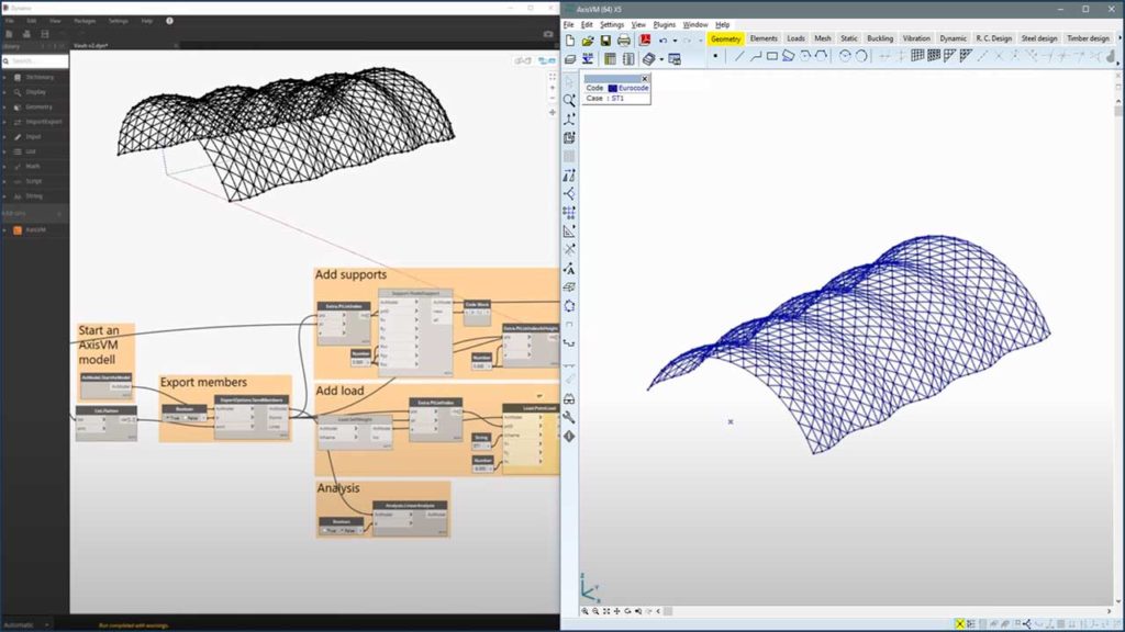
AxisVM Export plugins allows users to export parametric models created in Grasshopper/Dynamo to AxisVM. AxisVM Export plugin should be installed in Grasshopper/Dynamo, and it communicates with AxisVM through its API (COM interface).
About FEM (Finite-Element Method)
The Finite-Element Method (FEM) is a computational method/technique developed by engineers used to obtain an approximate solution to engineering problems. Finite element breaks a complex problem into simpler problem and uses a mathematical glue to join the solutions.
An engineer designing a bridge will need to know how the proposed structure will behave under load. The equations describing the distribution of structural stresses are known but they can’t be directly solved for a complicated shape such as a bridge. However the equations can be solved for very simple shapes like triangles or rectangles. The finite element method takes advantage of this fact. We replace the single complicated shape with an approximately equivalent network of simple elements. The overall pattern of elements is referred to as the finite element mesh. And this pattern will be unique to each new problem. The initial step is to design this mesh. And for this we must first decide what kind of elements will use.
What’s new in version X6:
General
- Smart command line and search.
- Enhanced selection filter.
Elements
- Parametric double wedged I, crossed I, SFB, IFB, symmetric and asymmetric HSQ profiles.
- Eccentric beams.
- Winkler-Pasternak elastic foundation.
Loads
- Displaying color-coded surface loads of all load cases of a load group in one view.
- Generating wind loads from a CFD model (new CFD module).
- Applying eccentric concentrated or distributed loads on beams and ribs.
- Rules to generate custom combinations in the table of critical load group.
- Defining the direction of spectra for seismic analysis.
Results and reports
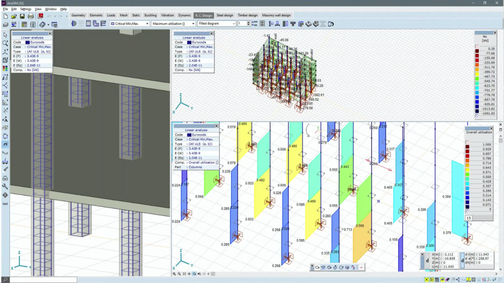
- Result display in rendered view.
Rendered view can display distribution of normal stress within the crosssection of a beam.
Rendered view can display top and bottom components of surface stresses, reinforcement amounts, crack width values simultaneously (RC1 module).
Design
- Utilization result component and diagrams for reinforced concrete columns (RC2 module).
Calculating required reinforcement for reinforced trapezoid steel decks. (RC1 module).
Shear design of reinforced concrete walls (RC5 module).
Design calculation report for reinforced concrete columns (RC2 module).
Integration
- New AxisVM components for Rhino/Grasshopper.
SAF interface imports and exports loads (SAF module).
Tekla interface imports and exports beam end releases, nodal and line supports (TI module).
For more information and a full list of new features please visit New features of AxisVM X6 Release 1.
About Inter-CAD
Inter-CAD facilitates a fast, efficient and transparent design process for structural engineering that meets the most up-to-date analysis and design requirements by developing AxisVM, an easy-to-use, comprehensive, and flexible software for civil engineers worldwide.
Gallery
©Inter-CAD
©Inter-CAD
©Inter-CAD
©Inter-CAD
©Inter-CAD
©Inter-CAD
©Inter-CAD