- Date added:
- Mar 04, 2022 | Last update check: 1 minute ago
- Integrations:
- —
- Licence:
- Freeware
- Runs on:
- AutoCAD 2018 / 2019 / 2020 / 2021 / 2022
LevelSet for AutoCAD is a free add-in that enables you to set original base point and create levels that automatically calculates level heights. It measures vertical distance from defined base point, and calculates the measured value through a level marker (e.g. on a slab). This task can be done with attributed data but with this add-in it is a lot faster and easier. All you have to do is just move level marker and it will recalculate the level heights. LevelSet can contain one or more Levels. Levels are created with following elements: Line, Text, Symbol (optional), and Leader (optional).
LevelSet is anonymous block (block name begins with *U). It holds also not displayed attribute with tag “LevelSet”. You can set name for each LevelSet by using this attribute.
LevelSet is similar to native AutoCAD Ordinate dimension with the following differences:
- LevelSet can contain more than one level.
- LevelSet base point can be defined as any positive or negative number. Ordinate dimension origin point is always 0.00 (zero).
- LevelSet level can be shown with the custom defined symbol.
Typical workflow:
- Create a new LevelSet. Go to Add-ins ribbon tab, and click the “LevelSet create” button. Or write RLCREATE or RL in command-line and press Enter.
- Set LevelSet properties. You can see the “LevelSet Properties” dialog window. It has similar settings as native AutoCAD dimension style manager. Go through four tabs – Lines and Symbols, Leader, Text, Units – and set properties. Here are some of the options:
- Lines and Symbols tab -> Symbol -> Default(Triangle): Set the default symbol for Level (block name _RLTRIA).
- Lines and Symbols tab -> Symbol -> User Symbol: Good practice to create user symbol is to draw all components on layer 0, color ByBlock in scale 1:1.
- Lines and Symbols tab -> Symbol Orientation -> Horizontally mirrored: If you use symmetrical symbol for example default triangle you won’tsee any graphical change.
- Lines and Symbols tab -> Symbol Orientation -> Rotate with Leader: To enable this option Leader must be checked on Leader tab.
- Leader tab -> Relative Base level: This value is added to vertical measurement from base point to the Level.
When you are ready click OK.
- Define level(s).
- Specify base point for LevelSet. Then specify Level end point.
- Specify base point of next Level. Then specify Level end point.
- Repeat until you define all levels. Press Esc to cancel.
Modification commands for LevelSet are available in the context menu (right click while LevelSet is selected). Levels contain intelligent data, similar to BIM software. If you start to move level up or down you’ll see that it recalculates numbers so you don’t have to worry about calculating that anymore. If you did want to, you can also move the leader line.
What’s new in version 2.3.0:
- Support for AutoCAD 2022.
About RS-BB apps
RS-BB apps is founded by Richard Stima. It provides plug-ins for AutoCAD available from the Autodesk Exchange Apps store, including free add-ins DimensionSet, LevelSet, and Xref Tools Extra.
Gallery
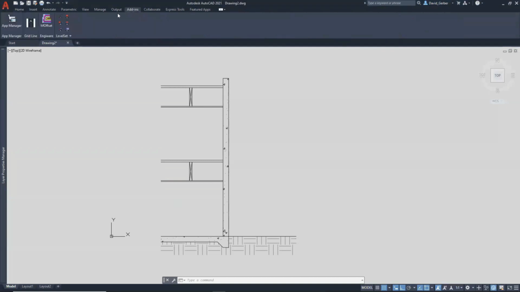
LevelSet tools in Add-ins ribbon tab. ©A2KTechnologies
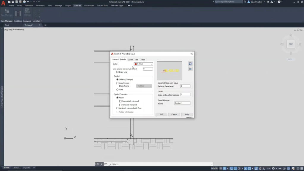
LevelSet Properties: Lines and Symbols tab. ©A2KTechnologies
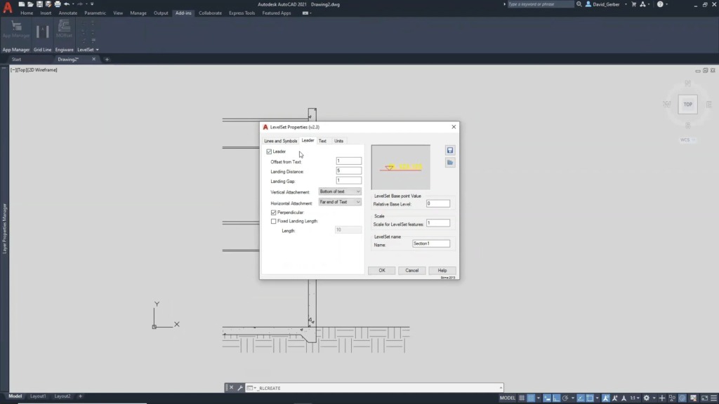
LevelSet Properties: Leader tab. ©A2KTechnologies
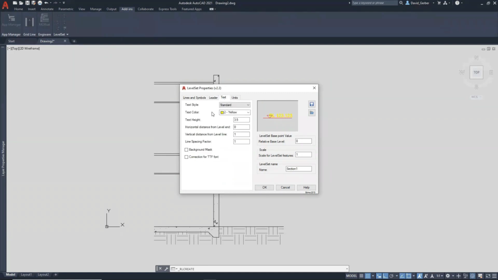
LevelSet Properties: Text tab. ©A2KTechnologies
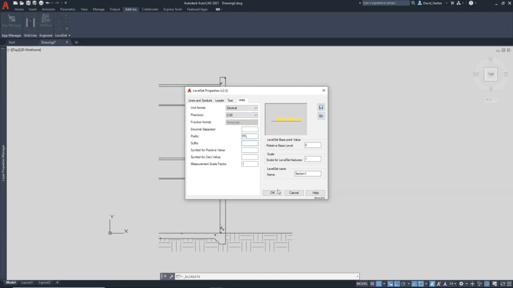
LevelSet Properties: Units tab. ©A2KTechnologies
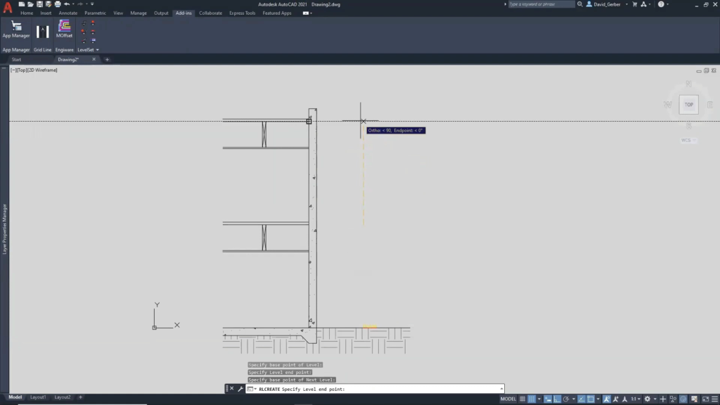
Specify base point and end point of Level. ©A2KTechnologies
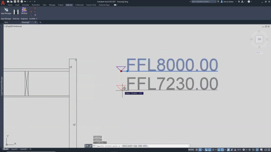
When you move level up or down it recalculates values. ©A2KTechnologies
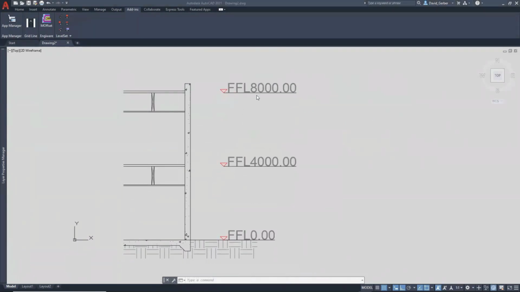
Created LevelSet. ©A2KTechnologies
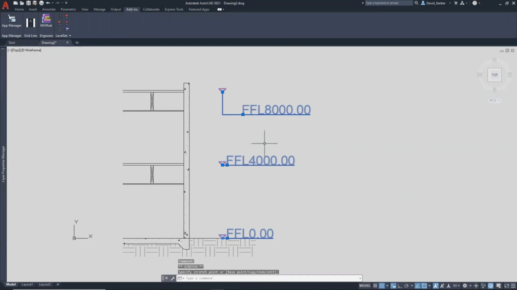
Levels can be modified by following grip points: Level base point, Level end point, Text (bottom-left justification) point. The location of LevelSet base point is displayed as two circles grip point; while holding the mouse at this point the defined value of the base point is displayed. ©A2KTechnologies
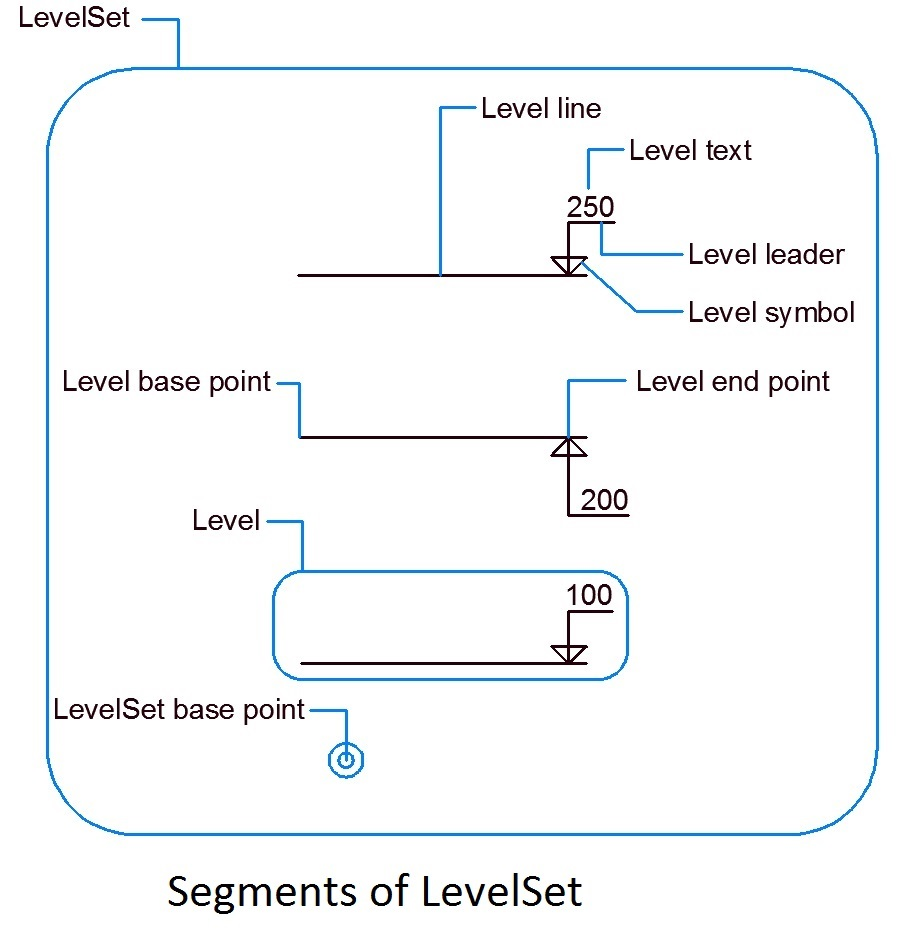
Segments of LevelSet. ©Autodesk