- File size:
- N/A
- Date added:
- Sep 27, 2022 | Last update check: 1 minute ago
- Licence:
- Trial
- Runs on:
- Revit 2020 / 2021 / 2022 / 2023
FrameLab for Revit is a coordination tool to create critical framing around openings and no-fly zones around MEP equipment. It can take you a lot of time to manually place framing around all your doors and windows, or place objects that represents clearances. With FrameLab add-in you can improve coordination by automatically framing your openings, and adding no-fly zones and tolerances. Clash detection software only detects clashes between two objects which means you need to have tolerances as geometry if you want for it to participate in clash detection process. These clashes (so-called “soft clashes”) maybe will not impact construction but will impact the facility operation. FrameLab works with your current Revit model as well as with linked models so you can easily control changes made by all team members and update your framings, no-fly zones and tolerances accordingly.
This tool gets full power when is used together with 3rd party software for clash detection such as ACC (Autodesk Construction Cloud) and Navisworks.
Typical workflow:
- Create critical framing. Use “Critical Framing” command to instantly create critical framing for all the openings in the entire model (walls, parts and assemblies). Specify sizes (depth, width, tolerance) and color for your framing. You can include elements from linked models. When you are ready click “Generate Critical Framing”. You will see generation results message with number of successfully generated critical framings and openings that failed to generate. You can navigate to those openings by ID and review it. If you want to remove generated critical framing use the “Delete Critical Framing” command.
- Create no-fly zones. Use “No Fly Zones” command to create no-fly zones early in the framing process. By creating no-fly zones you specify the areas where MEP engineers should not place any ductwork. If they place any ductwork there it will be recognized as clash in Navisworks. It is suitable for separating fire-rated areas where you don’t want to have ducts placed, or as a placeholder for structural or MEP elements. With no-fly zones you can easily control where you want certain items to be placed. There are two no-fly zone types you can choose: “Top of wall” or “Side of wall”.
- Tolerances. Use “No Fly Zones Tolerance” command to create tolerances around MEP equipment for accessing and maintenance. You can also use this command to create no-fly zones around revolving doors. Set tolerance and frame color, select elements, and click “Generate No Fly Zone”. If you want to remove generated no-fly zones and tolerances use the “Delete No Fly Zone” and “Delete No Fly Zone Tolerance” commands.
- Generate report. Use “Reports” command to regularly run reports so you can track changes and compare items. Compare previous reports or current model with previous model. You can approve or reject changes, or flag it for review. You can also see what is changed for every element (type, dimension, location, etc.). Reports can be exported as CSV, PDF or ZIP file.
Gallery
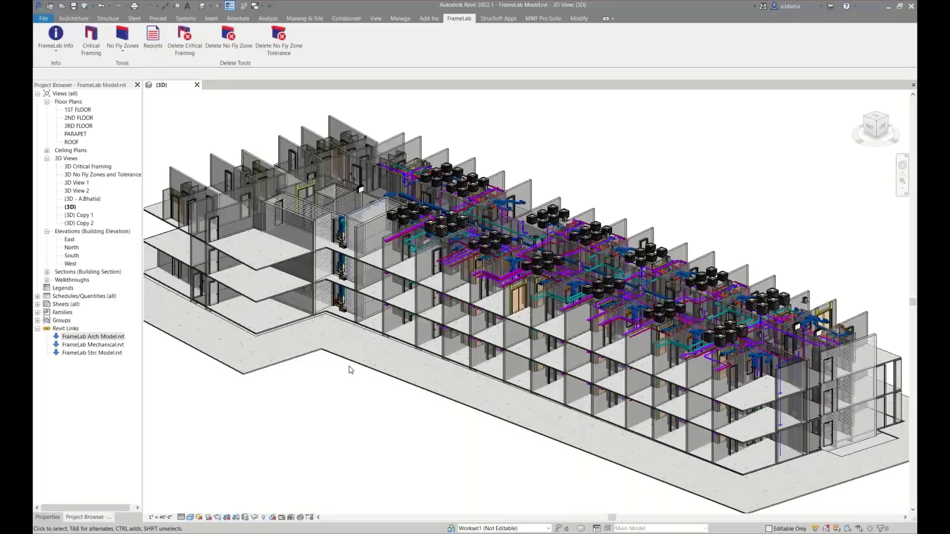
FrameLab ribbon tab in Revit. ©StrucSoft
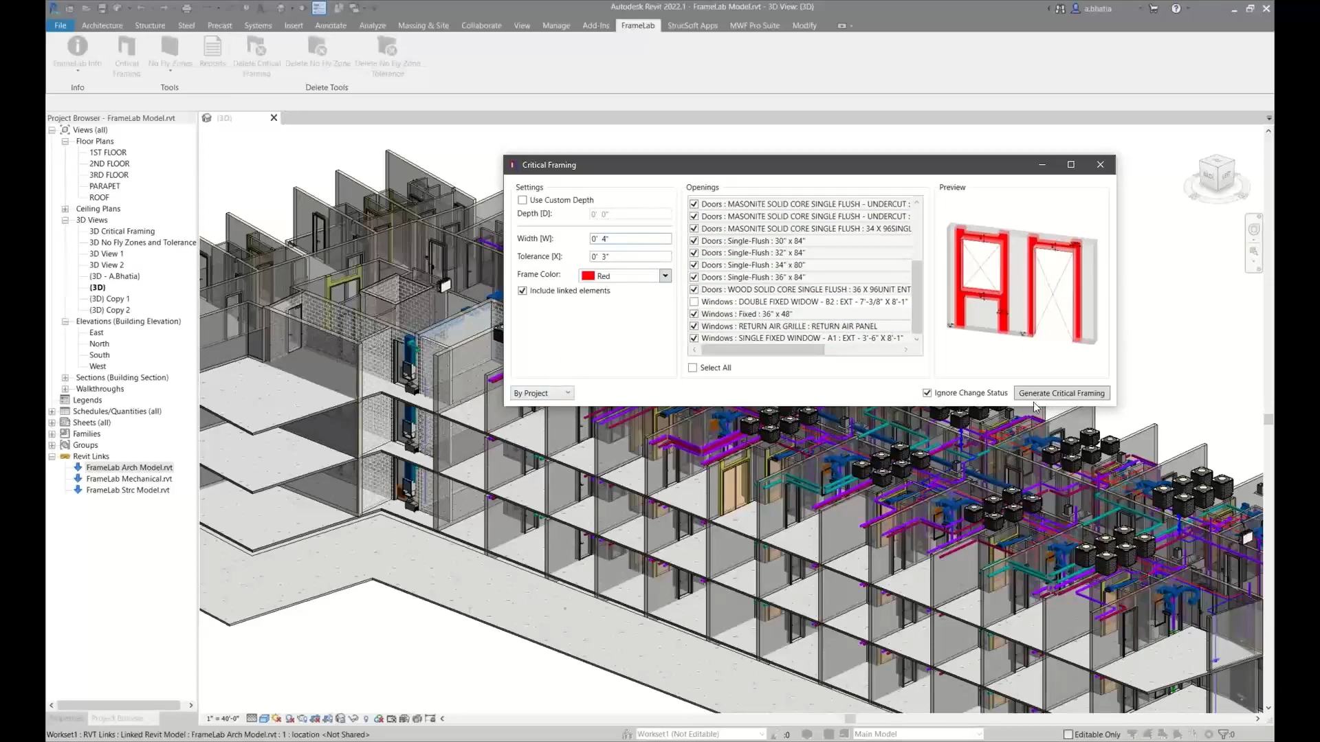
Critical Framing dialog box. ©StrucSoft
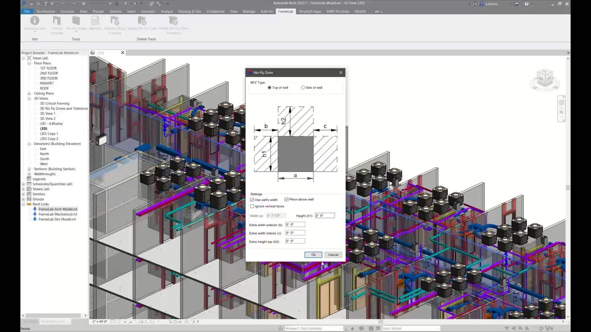
No Fly Zone dialog box. ©StrucSoft
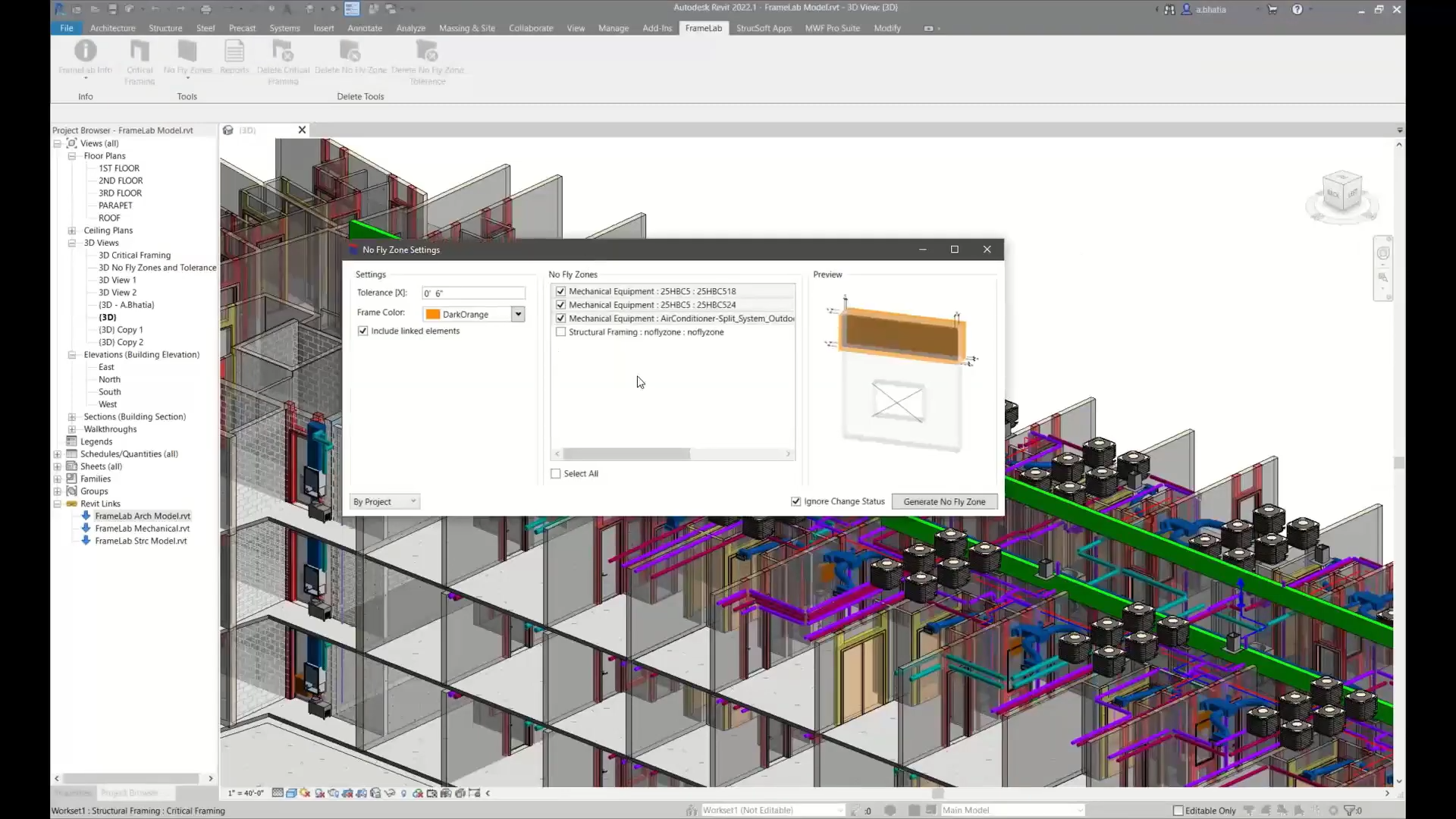
No Fly Zone Tolerance dialog box. ©StrucSoft
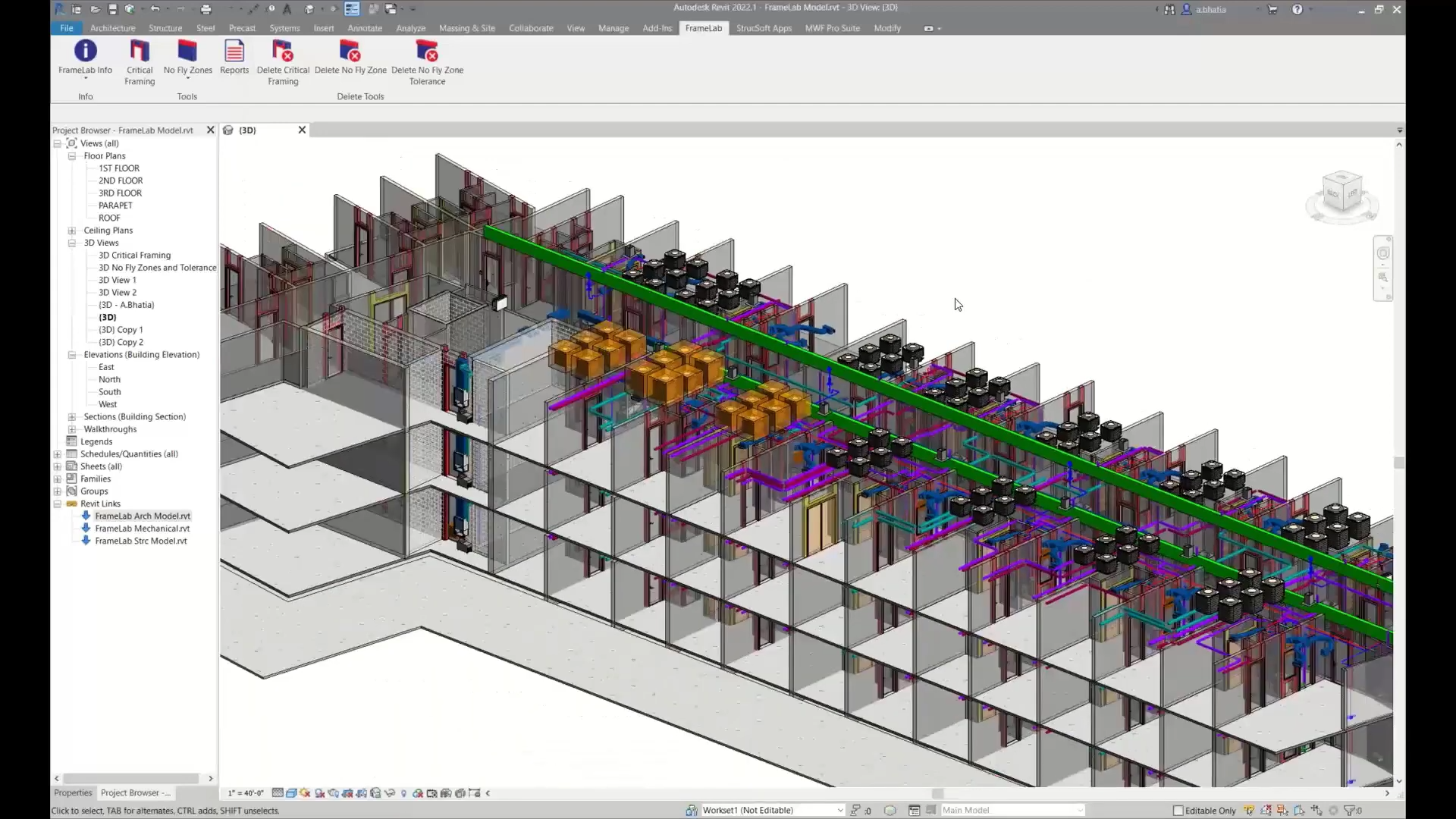
Revit model with critical framings, no-fly zones and tolerances. ©StrucSoft
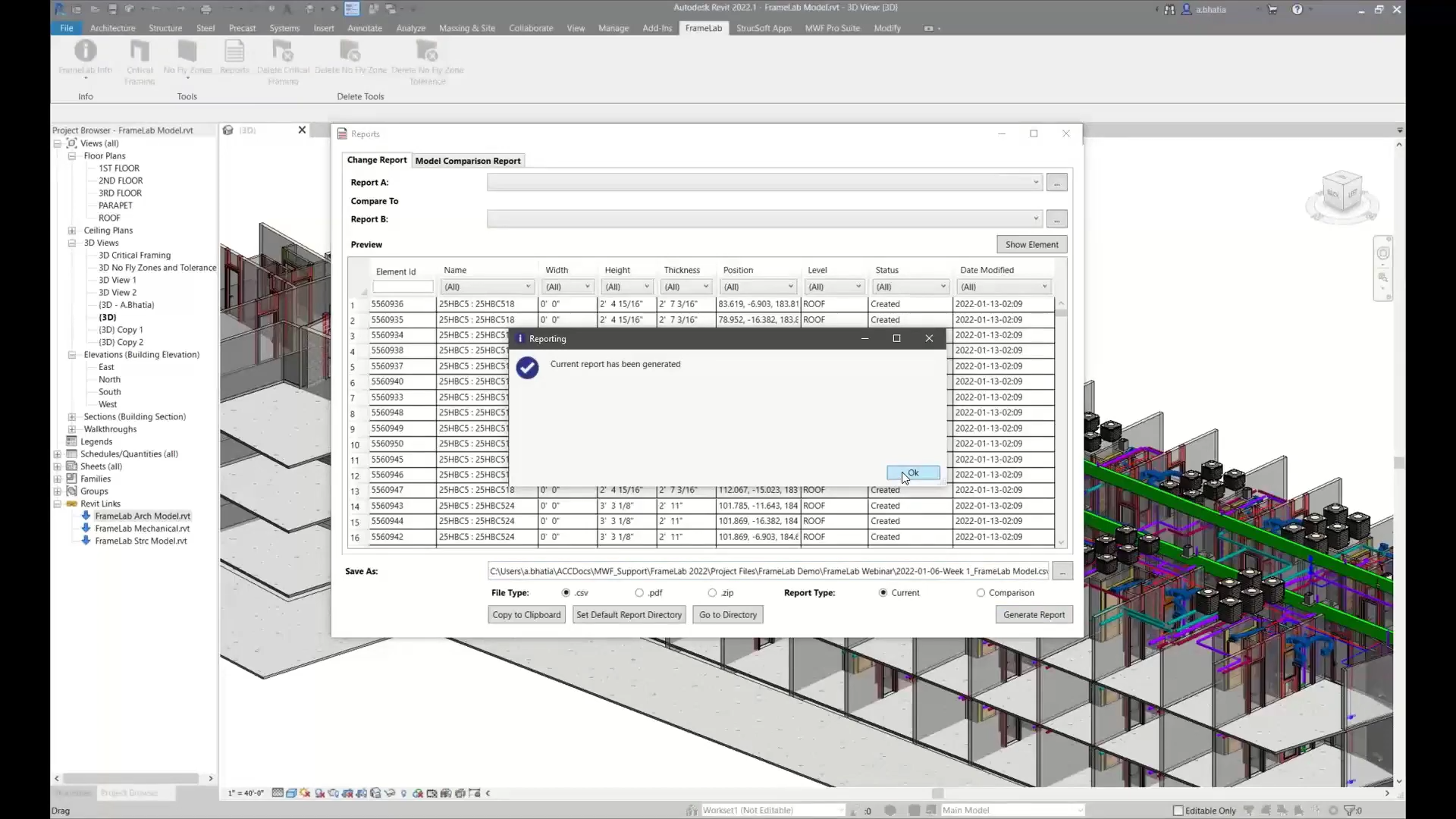
Generate change report. ©StrucSoft

Generate model comparison report. ©StrucSoft